
Table of contents
1Introduction
1.1General
The Enterprise Services Builder, commonly referred to as the Repository is the area in PI where the definitions of the messages are placed, alongside with mapping information, etc.
1.1.1What is it for?
-Loaded structure information for IDocs (loaded from an SAP system) (Imported Objects)
-Definitions of XML messages in XSD, WSDL, etc. format (External Definitions)
-Self created XML definitions (Data Types)
-Message definitions (Message Types) which are basically just a package around a data type with the ability to add a namespace.
-Service Interface / Message Interface (in PI 7.0). These interfaces use a Message Type to define the message, and then define the direction and type of the message.
-Message Mappings, the standard conversion of data in PI
-XSLT Mappings (Imported Archives) which are loaded using ZIP files which contain .xsl or .xslt files
-Operation Mappings which connected two Service/Message Interfaces and define all the mapping steps in between, the most commonly used are XSLT, Message Mapping or an ABAP class
-Integration Processes (BPMs) for advanced message control
1.1.2What is it not for?
-Definitions of Products and Software Components (SLD)
-Definitions of Business Systems and Communications (Configuration/ Directory)
-Proxy definitions and coding (R/3 on target or source system)
-IDoc setup (R/3 on target or source system)
-Destinations (SM59 on ABAP stack on PI system)
-Connecting interfaces (Config/Directory)
1.2Difference XI 7.0 and PI 7.1
1.3Getting Started
To create an object press the button at the top left to ‘Create Object’:

When this is done you’ll get a list of all objects that you can create in the Design area:

You can click open the sublists, one at a time. We’ll go over some of the most commonly used objects later.
You can create everything ranging from a namespace to a data type, however Software Component Version should _always_ be imported from the SLD.
2Work Areas
2.1Software Component Version (SWCV)
To add a new SWCV create a new object and select ‘Software Component Version’ under ‘Work Areas’.
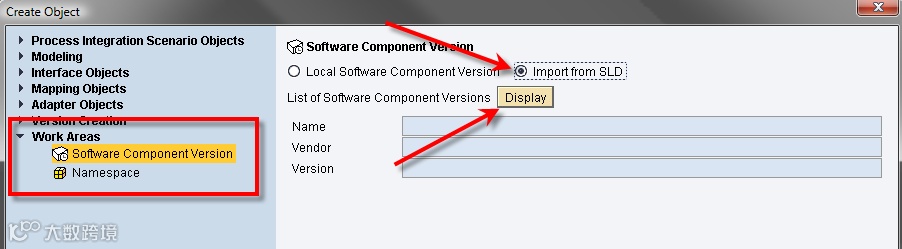
Note that you always need to import your SWCV from the SLD, it is highly not done to create a local SWCV for anything other than irrelevant testing.
Once you select ‘Display’, it will start importing the list of all available SWCV’s from the SLD, this may take a while.

Select your SWCV and select ‘Import’:

You’ll go back to the original window, select ‘Create’ here.
When your SWCV is imported from the SLD, it will allow you to enter some configuration for the object such as which R/3 system it should import IDocs and RFCs from (this can be changed later, regardless of IDocs already imported, so don’t worry), if the objects are modifiable and if the objects are original. You’ll also have to specify an original language:

The ‘Objects are Modifiable’ is to allow objects to be changed if they are inside this SWCV. In all QAS and PRD systems, this should be turned off. If you need to make an emergency change, you have to change the SWCV and unflag this checkbox.
2.2Namespaces
To create a namespace select it under work areas when creating an object:

You’ll need to add the namespace name, the naming convention is usually:
http://
However, many companies use their own naming conventions for these, so when in doubt, just follow the other namespaces in the PI system.
3Interface objects
3.1Data type
A data type is strictly speaking just that, a definition or type of data. It only tells you what format the data will be in. Fields entered here detail if something is mandatory, the format it is, if it has children or parent nodes, etc.
For example, you can create this data type:

And then simply add some nodes using the ‘Insert New Lines’ button.

For starters you just add rows:

But you have to define a ‘Type’ as well, usually we take the xsd:string type, just select it:

After giving all your rows a type (it’s mandatory) you can change their occurrence or add details, for example we want all fields to be mandatory except the date of birth:

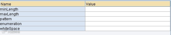
In the details column you can add additional information to validate your XML:
Once you save your data type, it should show up under your SWCV:
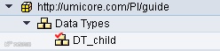
The ‘v’ next to the object icon means it’s not yet activated. As long as something is not activated, it will not be used by PI. If there are older versions of the object available, those will still be used of course.
You can also nest data types, to create more complex structures. You can also use data types within data types:

To do that, simply drag the data type into the ‘type’ column of the node.
3.1.1Specific Types
Some Data Types have a specific fashion in which they need to be built. The most common among these are:
3.1.1.1CSV-file
A Data Type always needs a parent to make it parseable to CSV. It’s this field (“Client” in the example) that you give the parameters in the Configuration that decide how your CSV will look (which delimiter, header fields, etc.).
For possible Data Type then would be (note that “Client” is the parent here):

Giving this as the resulting XML-file:
001
Will give this as CSV-file if you use pipe (“|”) as delimiter:
001|Delaware|Consulting
Kennedypark|4|8500|Kortrijk|België
3.1.1.2Database record
There’s a difference between the Data Type for an inbound message (to the database) or an outbound message (from the database).
If you’re sending a file to the database, you’ll have to take into account that the message structure is very specific. Back to our example, it would look like this:

Most of these fields have specific values. The parent (named tbl_TableName in the example) is generally named after the table name (in this case the table name is: “tbl_TableName”). This is optional but easy to use and easy to work with.
The “action” field is an attribute, not an element. It’s optional and in the mapping you’ll likely fill it with UPDATE_INSERT (which means you’ll add a table line or update an existing one). There are more possible values than UPDATE_INSERT though that one is the most commonly used one.
The “table” field is filled with a constant: the table name. In this case: “tbl_TableName”.
The “access” field is the actual contents of the table. The occurrence is 0..1 and the fields in it, the actual columns of the table need to named exactly like they are in the table (or you’ll get errors or the fields won’t fill up properly). Key fields are always optional, the others are possibly optional, this will be defined in the database (as NOT NULL or NULL).
The “key1” field contains all the fields that are used to decide the key of the line. This also needs to be consistent with the database. These fields are also required.
If you’re receiving data from a database, the structure is a lot more simple. You’ll only need a parent named “row” with an occurrence of 0..unbounded. This is needed to be able to read multiple database rows (which is rather likely).
Like this:

The actual SQL Query you’ll use to get the data out of the database will be in the Communication Channel.
3.1.1.3BAPI
If you’re using BAPI’s you’ll most likely (preferably) be using a Proxy. If you use a Proxy your destination message (the inbound interface) can look exactly like your source message. The Proxy will read it to an internal table and do the work for you. (sort of, you still have to write the Proxy …)
You can also import a BAPI the same you would import an IDoc. Only you have to import an RFC (Remote Function Call) not an IDoc.
3.2Message type
A Message Type holds just one Data Type and never more. Message Types are used by the Message Mapping and by the Message Interface.
It is however possible to use more than one (or one, several times) Message Type per Message Mapping.
To create a Message Type create the appropriate object, note, you can also click any of the other object titles once they’re created to create any other new object:

Creating a message type makes you choose a name for it, and like with data types a SWCV and a namespace:
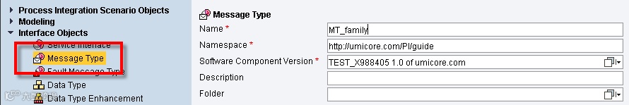
When you created a message type you need to select a data type to use. You can also change the namespace of the XML you’ll be creating, by default, your SWCV namespace is used:


This is all you need to do to create a message type. Not that message types are only used by Message Mappings and other mapping objects. They won’t show up in the Configuration for example (only interfaces are worked with there)
3.3Fault Message Type
A fault message type is a standard structure used to send error messages back and forth to for example Proxies or Enterprise services.
For example when you create an inbound message for a Proxy, you should attach a FMT. The structure used by a FMT is created automatically, you just get to decide on the name:


This is automatically created, you just need to ‘Save’ afterwards, when you get the following message, just press ‘Create’ (you will not always get this message):

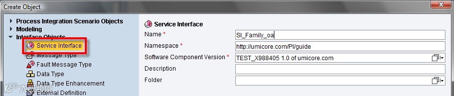
3.4Message Interface (XI 7.0) = Service Interface (PI 7.1)
The service interface is the message we defined in the Message Type but this time defined with a direction/category and a communication mode/mode.
The direction is either Outbound (PI receives the message) or Inbound (PI delivers the message, after mappings). The direction can also be ‘Abstract’ in which case the message is neither inbound or outbound, but is used by a BPM or Integration Process.
To define a Service Interface, create a new interface and select the Service Interface object:
When this is created you have to choose first, a category:
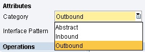
And then a mode:

Synchronous message have a return, and will require the receiving system to do processing and give a return message. Asynchronous messages just deliver a message to a system and won’t wait for the system to confirm delivery or processing.

Then you can drag your Message Type from the list onto this line, and it should show you Message Type.
This is all we need to configure for Interface Objects.
FOR MORE INFORMATION ON THE USE OF METHODS/SERVICE OPERATIONS, PLEASE VIEW THE APPENDIX AT THE END OF THIS DOCUMENT. ENTRY FOR ‘SERVICE OPERATIONS’
4Mapping objects
4.1Message Mapping
The Message Mapping is the most commonly used type of mapping by Operation Mappings (we’ll get to that later). A message mapping uses a source message and target message (both in XML format, be it through Data Types, imported XSD’s, IDocs or others) and converts the data in those messages.
To create a message mapping create an object of the Message Mapping type under Mapping objects:

We start with an empty Message Mapping. The idea is to drag Message Types from the column in the left to the left and right part of this new Message Mapping, more specifically, here:

Simply drag messages there and you should see the XML tree appear below:

Now there are a few important things to note:
·Note the occurrence column. This is the occurrence for a node. This is 0..1, 1..1, 0..unbounded or 1..unbounded. Nodes with a 1 as starting concurrence will always be mandatory. They also need no mapping to be generated, they will also be there.
·This also means that mandatory children of mandatory parents must always have data in them. These are represented by the red dots in front of their names (see the target structure (on the right))
·There are several buttons at the top:

1.View only the tree
2.View the tree + the other columns
3.View the source code of the XML (so the XSD)
4.Expand or collapse the entire tree or a specific node
5.Shows the full path (for example an ‘ns:0’ before the XML node, etc.)
6.Filter the tree, which means it’ll only shows nodes that have a mapping or are mandatory
7.Shows the mapping column (for the nodes that have one, this is only available in the target structure, not in the source structure)
8.Shows the selection column
9.Searches the node for a specific node (on name only)
10.Save the document source
·At the top are several more button:

1.The current tab, where the mapping is done
2.You can copy paste XML into the Test tab to test your mapping
3.You can define specific attributes of the message type here, like how many of each message type occurs, possible multiple message types, etc.
4.Java functions that can be used
5.Select a message for use with the mapping, for both source and target
6.Select two nodes in the source and target structure and press this button. This will map the two nodes, and ALL the nodes under those nodes if they have identical names
7.Clear the mapping (careful!)
8.Data flow editor, which is what we’ll be using to program the actual mapping
9.Text preview
10.Show which templates you used (not used often)
11.Shows the dependencies
12.Show suitable templates
13.Create a template based on the mapping
4.1.1“Building Blocks”
Note: We changed the cardinality of the target structure to 0..unbounded
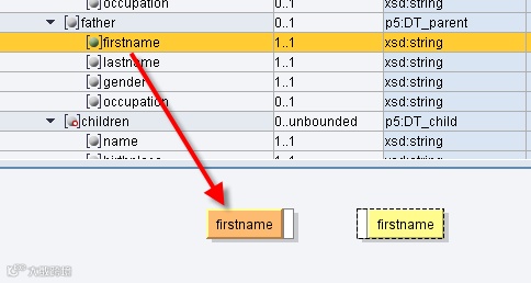
To map something using Message Mapping, you can simply drag it from the left column to the right column:

This should result in this being displayed at the bottom:

To view the mapping ‘to’ any specific node, just double click the target node. For example the ‘firstname’ node currently has no mapping.

There are several colors used to define the mapping. Grey which means nothing is mapped, nor is anything mandatory for this node. Yellow means the mapping is incomplete. Green means it is incomplete. Red means the mapping is not complete and mandatory. Orange means the blocks are not used in the current mapping.
So after double clicking ‘firstname’ under ‘owner’ in my target structure (House) and then dragging ‘firstname’ for the father in the source structure onto the mapping field, this is what you get:
Note several things happened:
-The circle before firstname became green, meaning it is now used in the mapping
-‘firstname’ on the right is still yellow because the mapping is incomplete
-‘firstname’ on the left is orange, because it is not currently used in the mapping (it is there, just not used)
To connect two nodes you draw a line between the exiting (on the right side) white bar to the entering (on the left side) white bar of the target node. This will form a link:
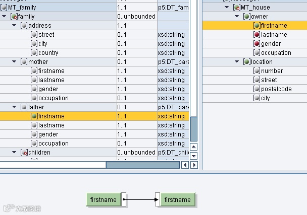
Now that this is done, both nodes are green as the mapping is complete, and in the right structure, the circle before my node became green (coming from red) to show that the mapping is complete.
This is the simplest of the mappings, as no conversion is needed. PI supplies a bunch of standard conversions, and for everything else there is the possibility to use user-defined functions (discussed later).
4.1.1.1Types of Blocks
There are several kinds of building blocks, each hold a group of functions which can be used, I’ll list the more important ones for these large groups:
-Arithmetic (add, subtract, multiple, etc. All the standard arithmetic functions can be found here)
oFormatNumber – Formats a number into a form you can specify (leading zeroes, trailing zeroes after comma, comma sign, etc.)
oRound – Returns the closest Initial value
-Boolean (This contains the checks, if, or, etc.)
oIf – Standard if function, a Boolean (true/false) must be entered and then two roads can be chosen
oIfWithoutElse – Only valid in ‘true’ situations
oNot – Returns true if false, false if true
-Text (Functions to modify text content)
oConcat – Concatenates two values, separated by a value you can enter (static, not dynamic)
oequalS – Checks if the entered string matches the second entered string
-Conversions (Functions to drastically change data)
oFixValues – Allows you to substitute a certain set of values for another set of values. These must be entered as static values
-Date (All date functions, only two are really important)
oThe date codes that can be used are:
§yyyy – 4-digit year
§yy – 2-digit year
§MM – month
§dd – day
§HH – hour (24 hour clock)
§hh – hour (12 hour clock)
§mm – minute
§ss - second
ocurrentDate – Returns the current date in the format you supplied
oDateTrans – Transforms the date of one type to another type, both to be specified
-Constants (These functions pertain to … constants, whether artificial or real does not matter)
oConstant – Allows you to enter a static variable for use in your mapping
oCopyValue – Copies the value of a header level so that all children may use it
-Node Functions (These are the most complex mapping blocks used, experimentation is the way to go if you want to familiarize yourself with these)
oremoveContext – Removes all contexts and puts everything into one large queue
oexists – Returns true or false, depending on if the node exists
oSplitByValue – Splits the value queue into contexts, with a new context every value, every changed value or every empty value
ocollapseContexts – Collapses the context so that all context changes are gone, and only the first entry of every different context is saved
omapWithDefault – Puts a given standard value if the node does not exist
-Statistic (This is a collection of statistics to be used in your mapping)
oSum – Returns the sum of all arithmetic nodes in the same context
oaverage – Returns the average of all arithmetic nodes in the same context
ocount – Returns how many nodes there are in a single context
oindex – Returns the current iteration of a source node
4.1.2Context Handling
Thanks to Riyaz Sayyad’s blog: https://www.sdn.sap.com/irj/scn/weblogs?blog=/pub/wlg/3537
Context handling is an important technique to map complex scenarios in XI. This weblog introduces the basics of context handling using a simple example.
Message mapping in XI works by means of queues. A queue contains an entire XML instance of the source message. Depending on the hierarchy in the source message, different nodes and elements can be categorized into different contexts. All the nodes and elements that belong to the same parent node are said to be in the same context. Hence, the nodes and elements that belong to different parent nodes have to be separated by a context change.
XI provides various node functions for context handling during message mapping. Let us understand the concept of contexts using a simple example. Consider the source message shown below:

Elements ItemNumber and MaterialNumber belong to the same parent node OrderItem, and hence are in the same context. Also, node OrderItem and element OrderNumber are under the same parent node OrderHeader, and hence are in the same context. Whereas, as elements ItemNumber and OrderNumber belong to different parent nodes, they fall under different contexts.
Following figure shows the OrderItem context. Context change is inserted after every occurrence of OrderItem. Grey colored rows correspond to context changes.

Following figure shows the OrderHeader context. Context change is inserted after every occurrence of OrderHeader.

Similarly, using the Customer context, inserts a context change after every occurrence of Customer.

If the Orders context is used, no context changes will be inserted as Orders is at the highest level in the hierarchy.

We can use explicit context selection as shown above or use the node functions available in the Graphical Mapping Editor.
Let us take an example where the use of contexts can be emphasized. In the source message shown above OrderNumber appears only once while OrderItem can occur multiple times within the OrderHeader node. Suppose we want to map OrderNumber multiple times in the target message, such that it is available under the target node corresponding to every sales order item. To do this, we can use the node function called useOneAsMany as described below:

The first input parameter expects the list of values that we want to propagate to the target message.
The second input parameter expects the number of iterations or how many times we want to replicate the value given in the first parameter.
The third input parameter is the list of context changes. Depending on this parameter the source values will be propagated to the target after every context change.
Note: For this function to work as expected, the first two parameters must contain the same number of contexts while the last two parameters must contain the same number of values.
In our case, the first parameter is OrderNumber, since we want to assign value of this element to the field in the target structure. Second parameter is OrderItem as it corresponds to the number of times sales order items would occur in the target structure. Note that both these parameters have the same number of contexts (See figure below). The third parameter is ItemNumber, which indicates the number of context changes. ItemNumber uses OrderItem context by default (since, OrderItem is the immediate parent node of ItemNumber). Hence, the value of first parameter will be assigned to the target every time the context change occurs for ItemNumber. Also note that the second and third parameter has the same number of values (See figure below).

We can see that the value 1100 (first parameter) has been replicated three times (second parameter) at every context change in third parameter.
There are many other node functions available within the Graphical Mapping Editor to aid the context handling in different scenarios. Graphical Mapping Editor also allows you to write your own functions wherein you can use methods of predefined classes to handle contexts.
4.1.3Changing message cardinality
To change the message cardinality in your message mapping go to the ‘Signature’ tab and change the occurrence column there.

Now if you go back to definition you’ll see two new parents: Messages and Message1.

Note: Because we changed the ‘root’ node of our message, the entire mapping already done will be lost. Always do occurrences at the very beginning of development, otherwise you will have a lot of rework (more if you didn’t make a separate mapping before you changed!).
4.2Imported Archive
The Imported Archive is a mapping program that is an XSL(T) document. They are uploaded in PI by archiving them into a ZIP-file, and then uploading that ZIP file. PI will read the ZIP file, and extract all mapping programs it finds inside that archive.
Because of this, it’s possible to add multiple XSL files in one archive and upload them in one go.
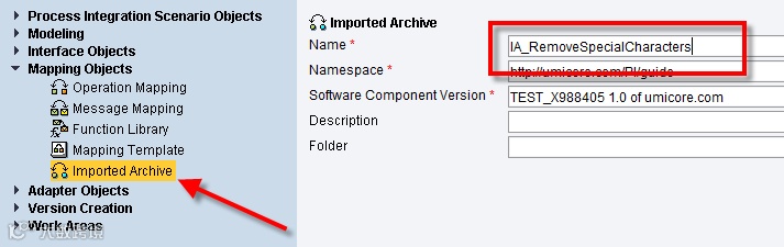
To create an Imported Archive, select New from the top:

Select ‘Imported Archive’ under Mapping Objects and enter a name, namespace and SWCV:

When you create your IA, you can upload a file to upload the program into your IA. When you press the ‘Import Archive’ button, you’ll be prompted with a selection window not unlike the Windows kind. Select your file of the ZIP-type and select ‘Open’.
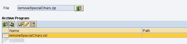
PI will automatically list all mapping programs in the archive.
4.3Interface Mapping = Operation Mapping
An Interface or Operation Mapping (IM/OM) connects an outbound interface to an inbound interface. It will extract the Message Types from the Message or Service Interfaces and then allow you to select mapping programs to happen between them.
You have to select at least one Mapping Program but there is no upwards limit.
To create an OM select ‘Operation Mapping’ under ‘Mapping Objects’.

You can simply drag the interfaces over their locations:
This should be your result:

Now to get to the Message Types, select ‘Read Operations’ and they will automatically be entered:

4.3.1Adding (multiple) mapping programs
To add multiple mapping programs, select the plus or minus at the top of the Mapping Program section. You can also change the type of mapping program you want to add:

This is an OM with two mapping programs:

4.3.2Changing the interface cardinality
To change the cardinality of the messages in the interfaces (to use a message mapping that supports this) simply change the value in the occurrence column:

5Scenario objects
5.1Abstract Interfaces
5.2Sending and Receiving
5.3Synchronous / Asynchronous Bridge
5.4Transformations
5.5Error Handling
6Appendix: Service Operations
6.1Service Interface
When you create a Service Interface it will hold one operation with the same name as the service interface as default. At least one operation is mandatory for any service interface.
Note that while you can’t remove or change it while it is the only operation in the service interface, it does not have to have the same name as the service interface. To change it however you need to add one, remove the first one, and add it again under a different name. There is no renaming possible (only deleting and recreating).

To add a second or third interface just go into change and click the ‘+’ under the Operations tab:


Don’t forget to set the Category to ‘Abstract’ (that way it can be used for either direction, this is easier, especially with services) and the Mode. For most Services it is standard to set them to Synchronous so you have a return you can set yourself.
6.2Operation Mapping
Note that as of PI 7.1 they changed the name of the Interface Mappign to Operation Mapping. This is because an Interface Mapping is required/possible for all operations. Thus, we need to create an Operation Mapping for every operation in the interface (unless of course we want no mapping whatsoever, then we leave this blank here and in the Interface Determination on the Configuration).
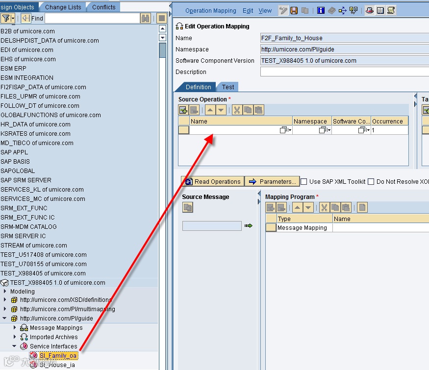
So first create a new empty Operation Mapping:

When you drag a Service Interface on the Source Operation, and multiple operations are available it will prompt you with a choice of all these operations. You simply have to select the opeation you want.

Then you finish your Operation Mapping in the way you want.
6.3Configuration
6.3.1Receiver Determination
The Receiver Determination is created as you should be used to:

Note that if you’re using multiple operations it is advised to always declare the Software Component in the Receiver Determination. It’s not mandatory here, but it’s good practice, and it’s mandatory for other components.
6.3.2Interface Determination
When you create an Interface Determination you’ll immediately notice that the ID is based on the Sender Interface:

This stays this way, as PI uses the sender Communication data and the Receiver Communication Party and Component as unique key identifiers for all its Configuration components.
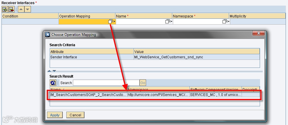
You’ll also note that when you try to select an Operation Mapping you can only view the Operation Mappings for the Interface & Operation with the same name!
There are seemingly no parameters to adjust so you can use more operations! You also can’t try to create a new ID for the new Operation as this won’t work.
What you’ll need to do is define the Software Component Version:

When you did this you get a list of all Operations in the Service Interface. When you select a different one, you can select a new Operation Mapping, and this time, it should work!
Note that as you only have one Interface, you only have one Receiver Agreement as well! This means that unless you make use of splitting in Receiver Determination, you’ll have to map both Operation Mappings to the same Receiver Interface.